SKU: Eaton-118702
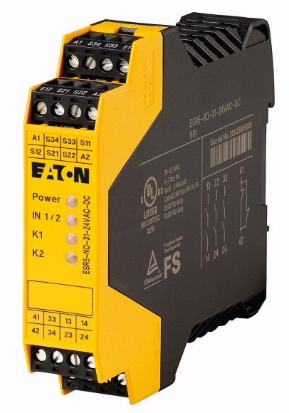
Safety relay emergency stop/protective door, 24VDC/AC, 3 enabling paths
Safety relay dual-channel, for implementing the basic functions emergency switching off, emergency stop, and protective door, supply voltage 24VDC or 24VAC 50/60Hz, 3 Enable current paths (IEC/EN 60204 Stop category 0), 1 signal current path, busbar tag shroud to EN 50274 with vertical actuation from the front finger- and back-of-hand proof, suitable for cat. 4 according to EN 954-1 / PL e according to EN ISO 13849-1 / SILCL 3 according to IEC 62061 / SIL 3 according to IEC 61508, degree of protection IP20, installation location IP54 minimum, TÜV tested, rated impulse voltage 4 kV / basic isolation (safe isolation, reinforced insulation and 6 kV between input current circuit and enable contacts.)
| Product range | Electronic safety relays |
| Basic function | Emergency stop; emergency switching off Protective door Feedback circuit |
| Mounting width | |
| Operation | 22.5 mm |
| Supply voltage [Us] | Automatic reset |
| Approval | single-channel dual-channel |
| Safety related characteristics | 24 V DC 24 V AC, 50/60 Hz |
| Enable current paths to IEC/EN 60204-1 Stop category 0 | |
| Signal current paths | Cat. 4 PL e according to EN ISO 13849-1 SILCL 3 according to IEC 62061 SIL 3 according to IEC 61508 |
| Intended use | |
| Policies List | 3 |
| Standards | 1 |
| Dimensions (W x H x D) | |
| Mounting width | Safety relay for monitoring emergency stop and protective door switch. Module used to safely interrupt electrical circuits. |
| Weight | EMV 2004/108/EG, Maschinen 2006/42/EG |
| Mounting position | EN ISO 13849-1:2008, EN 62061:2005+AC:2010, EN 61508, Parts 1-7:2001, EN 50178:1997, EN 60204-1:2006+A1:2009 |
| Mounting | 22.5 x 99 x 114.5 mm |
| Connection type | 22.5 mm |
| Lifespan, mechanical [Operations] | 0,23 kg |
| Terminal capacity >Solid |
As required |
| Terminal capacity >Flexible with ferrule |
Top-hat rail IEC/EN 60715, 35 mm |
| Terminal capacity >Solid or stranded |
M3 screw terminals |
| Terminal screw >Pozidriv screwdriver |
10 x 106 |
| Terminal screw >Standard screwdriver |
1x (0.2 – 2.5) 2x (0.2 – 1) mm2 |
| Terminal screw >Max. tightening torque |
1x (0.25 – 2.5) 2x (0.25 – 1) mm2 |
| Stripping length | 24 - 12 AWG |
| Material | 2 Size |
| Duty factor | 0.6 x 3.5 mm |
| Operating conditions >Climatic environmental conditions >Climatic proofing |
0.6 Nm |
| Operating conditions >Ambient temperature >Operation [ϑ] |
7 mm |
| Operating conditions >Ambient temperature >Storage [ϑ] |
Housing: polyamide PA not reinforced Contacts: Material: silver tin oxide, gold plated (AgSnO2, 0.2 µm Au) |
| Operating conditions >Ambient temperature >Condensation |
100 % DF |
| Operating conditions >Atmospheric conditions >relative humidity |
Cold to EN 60068-2-1 Dry heat to IEC 60068-2-2 Damp heat as per EN 60068-2-3 |
| Operating conditions >Atmospheric conditions >Air pressure (operation) |
-20 - +55 °C |
| Operating conditions >Atmospheric conditions >Altitude [Above sea level] |
-40 - +70 °C |
| Power loss [P] | Non-condensing |
| Degree of protection to VDE 0470-1 >Enclosures |
Max. 75 % |
| Degree of protection to VDE 0470-1 >Terminals |
795 - 1080 hPa |
| Degree of protection to VDE 0470-1 >Degree of Protection |
2000 m |
| Degree of protection to VDE 0470-1 >B10d [switching cycles] |
5.16 W |
| Protection against direct contact when actuated from front (EN 50274) | |
| Vibrations (IEC/EN 60068-2-6) | IP20 |
| Clearance in air and creepage distances | IP20 |
| Rated impulse withstand voltage [Uimp] | Installation location: ≥ IP54 |
| Insulation | 300000 |
| Overvoltage category/pollution degree | Finger and back-of-hand proof |
| Stop category [according to EN60204-1] | 10 - 150 Hz Amplitude: 0.15 mm Acceleration: 2 g |
| Technical safety parameters: >Values according to EN ISO 13849-1 >Performance level [according to EN ISO 13849-1] |
EN 50178, UL 508, CSA C22.2, No. 14-95 |
| Technical safety parameters: >Values according to EN ISO 13849-1 >Category [according to EN ISO 13849-1] |
4000 V AC |
| Safety integrity level claim limit [in accordance with 62061] | Basic isolation Safe isolation, reinforced isolation, and 6 kV between input circuit and enable current paths. |
| Safety integrity level [In accordance with IEC 61508] | III/2 |
| Probability of failure per hour [PFHd] | 5,05 |
| Prooftest High Demand | PL e |
| Demand level | Kat. 4 |
| Prooftest Low Demand | SILCL 3 |
| Lifetime | SIL 3 |
| Rated operational voltage [Ue] | 5.05 x 10⁻¹⁰ |
| Rated operational voltage [Ue] | 240 Months |
| Permissible range | < 12 Months |
| Rated insulation voltage [Ui] | 66 Months |
| Quadratic summation current | 240 Months |
| Notes | 230 V AC |
| Inrush current | 24 V AC, 24 V DC V |
| Minimum switching capacity | 0.85 - 1.1 x Ue |
| Power supply circuit >AC operated 50/60 Hz |
250 V AC |
| Power supply circuit >DC operated |
72 A2 (ITH2 = I12 + I22 + I32) A2 |
| Fuse for control circuit supply >24 V |
Observe derating curve → Engineering |
| Rated current | min - max0.025 - 6 A |
| Current consumption | 0.4 W |
| Voltage at input, starting and feedback circuit | |
| Max. resistive load of the cable [R] | 3.4 W |
| Short-circuit current | 1.6 W |
| Pick-up time (K1, K2) for UN automatic mode, typical [tA] | short-circuit proof |
| Pick-up time | |
| Reset time (K1, K2) for UN , normally [tR] | S12, S22:30, S34:45 mA |
| Recovery time [tW ] | AC: 140 DC: 65 mA |
| Simultaneity for inputs 1/2 [tsync] | Approx. 24 V DC |
| Maximum permissible total cable resistance (input and starting circuits for UN) [RL] | ≦ 50 Ω |
| Maximum switching frequency | 2.3 A |
| Status indication | 100 ms |
| Contact type >Non-delayed enable current paths |
at Ue in automatic mode: normally 100 ms |
| Contact type >Delayed signal current path |
45 (single-channel) 10 (dual-channel) ms |
| Switching voltage | Approx. 1000 ms |
| Limiting continuous current | ∞ ms |
| Short-circuit protection for output circuits, external | approx. 50 Ω |
| Output fuse >NEOZED (N/O) |
0.5 Hz |
| Output fuse >NEOZED (N/C) |
Green LED |
| Maximum breaking power >Resistive load (τ = 0 ms) >24 V DC |
|
| Maximum breaking power >Resistive load (τ = 0 ms) >48 V DC |
3 |
| Maximum breaking power >Resistive load (τ = 0 ms) >110 V DC |
1 |
| Maximum breaking power >Resistive load (τ = 0 ms) >220 V DC |
min – max15 - 250 V AC 15 - 250 V DC |
| Maximum breaking power >Resistive load (τ = 0 ms) >250 V AC |
perN/O: 6 N/C: 6 A |
| Maximum breaking power >Inductive load (τ = 40 ms) >24 V DC |
Fuse 6 A gL/gG |
| Maximum breaking power >Inductive load (τ = 40 ms) >48 V DC |
10 gL/gG |
| Maximum breaking power >Inductive load (τ = 40 ms) >110 V DC |
6 gL/gG |
| Maximum breaking power >Inductive load (τ = 40 ms) >220 V DC |
144 W |
| Switching capacity | 288 W |
| Switching capacity >AC-15 >230 V |
77 W |
| Switching capacity >DC-13 >24 V |
88 W |
| Further information (flip catalog) | 1500 VA |
| Emitted interference | 48 W |
| Interference immunity | 40 W |
| Rated operational current for specified heat dissipation [In] | 35 W |
| Heat dissipation per pole, current-dependent [Pvid] | 33 W |
| Equipment heat dissipation, current-dependent [Pvid] | In accordance with IEC 60947-5-1 |
| Static heat dissipation, non-current-dependent [Pvs] | 4 A bei 360 S/h 3 A bei 3600S/h A |
| Heat dissipation capacity [Pdiss] | 4 A bei 360 S/h 2.5 A bei 3600S/h A |
| Operating ambient temperature min. | description |
| Operating ambient temperature max. | |
| 10.2 Strength of materials and parts >10.2.2 Corrosion resistance |
In accordance with EN 61000-6-4 |
| 10.2 Strength of materials and parts >10.2.3.1 Verification of thermal stability of enclosures |
In accordance with EN 61000-6-2 EN 662061_x |
| 10.2 Strength of materials and parts >10.2.3.2 Verification of resistance of insulating materials to normal heat |
|
| 10.2 Strength of materials and parts >10.2.3.3 Verification of resistance of insulating materials to abnormal heat and fire due to internal electric effects |
0 A |
| 10.2 Strength of materials and parts >10.2.4 Resistance to ultra-violet (UV) radiation |
0 W |
| 10.2 Strength of materials and parts >10.2.5 Lifting |
0 W |
| 10.2 Strength of materials and parts >10.2.6 Mechanical impact |
5.16 W |
| 10.2 Strength of materials and parts >10.2.7 Inscriptions |
0 W |
| 10.3 Degree of protection of ASSEMBLIES | -20 °C |
| 10.4 Clearances and creepage distances | +55 °C |
| 10.5 Protection against electric shock | |
| 10.6 Incorporation of switching devices and components | Meets the product standard´s requirements. |
| 10.7 Internal electrical circuits and connections | Meets the product standard´s requirements. |
| 10.8 Connections for external conductors | Meets the product standard´s requirements. |
| 10.9 Insulation properties >10.9.2 Power-frequency electric strength |
Meets the product standard´s requirements. |
| 10.9 Insulation properties >10.9.3 Impulse withstand voltage |
Meets the product standard´s requirements. |
| 10.9 Insulation properties >10.9.4 Testing of enclosures made of insulating material |
Does not apply, since the entire switchgear needs to be evaluated. |
| 10.10 Temperature rise | Does not apply, since the entire switchgear needs to be evaluated. |
| 10.11 Short-circuit rating | Meets the product standard´s requirements. |
| 10.12 Electromagnetic compatibility | Does not apply, since the entire switchgear needs to be evaluated. |
| 10.13 Mechanical function | Meets the product standard´s requirements. |
| Model | Does not apply, since the entire switchgear needs to be evaluated. |
| Suitable for monitoring of position switches | Does not apply, since the entire switchgear needs to be evaluated. |
| Suitable for monitoring of emergency-stop circuits | Is the panel builder´s responsibility. |
| Suitable for monitoring of valves | Is the panel builder´s responsibility. |
| Suitable for monitoring of optoelectronic protection equipment | Is the panel builder´s responsibility. |
| Suitable for monitoring of tactile sensors | Is the panel builder´s responsibility. |
| Suitable for monitoring of magnetic switches | Is the panel builder´s responsibility. |
| Suitable for monitoring of proximity switches | The panel builder is responsible for the temperature rise calculation. Eaton will provide heat dissipation data for the devices. |
| Type of electric connection | Is the panel builder´s responsibility. The specifications for the switchgear must be observed. |
| Rail mounting possible | Is the panel builder´s responsibility. The specifications for the switchgear must be observed. |
| Rated control supply voltage Us at AC 50HZ | The device meets the requirements, provided the information in the instruction leaflet (IL) is observed. |
| Rated control supply voltage Us at AC 60HZ | |
| Rated control supply voltage Us at DC | |
| Voltage type for actuating | Basic device |
| With detachable clamps | Yes |
| Evaluation inputs | Yes |
| With start input | No |
| With muting function | No |
| With feedback circuit | No |
| Release-delay | No |
| Number of outputs, safety related, undelayed, with contact | No |
| Number of outputs, safety related, delayed, with contact | Screw connection |
| Number of outputs, safety related, undelayed, semiconductors | Yes |
| Number of outputs, safety related, delayed, semiconductors | 0 - 26.4 V |
| Number of outputs, signalling function, undelayed, with contact | 0 - 0 V |
| Number of outputs, signalling function, delayed, with contact | 0 - 0 V |
| Number of outputs, signalling function, undelayed, semiconductors | AC/DC |
| Number of outputs, signalling function, delayed, semiconductors | Yes |
| Category according to EN 954-1 | One- and two-channel |
| Type of safety acc. IEC 61496-1 | Yes |
| Stop category acc. IEC 60204 | No |
| Performance level acc. EN ISO 13849-1 | Yes |
| SIL according to IEC 61508 | 0 - 0 s |
| With approval for TÜV | 3 |
| With approval for BG BIA | 0 |
| With approval according to UL | 0 |
| Width | 0 |
| Height | 1 |
| Depth | 0 |
| Product Standards | 0 |
| UL File No. | 0 |
| UL Category Control No. | 4 |
| CSA File No. | None |
| CSA Class No. | 0 |
| North America Certification | Level e |
| Degree of Protection | 3 |
| Characteristic curve | Yes |
Tüm hakları saklıdır. Mnelko Endüstriyel San. ve Tic.Ltd.Şti. 2024