SKU: Eaton-116020
Bus termination, SmartWire-DT, for flat cable
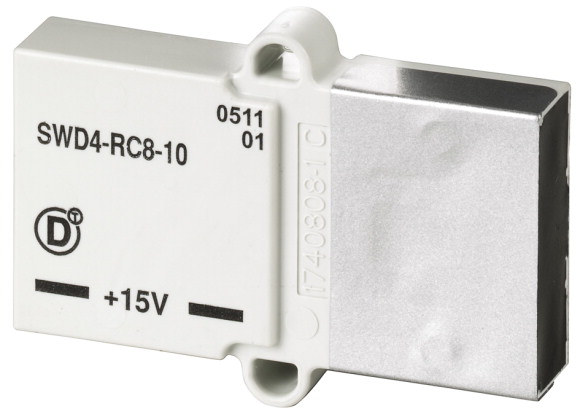
SmartWire-DT bus termination, is plugged into the SWD ribbon cable SWD4-8MF2 on the end of the SWD flat cable
| Product range | SmartWire-DT accessories |
| Basic function | Network terminator |
| Function | For the SmartWire-DT bus termination on the SmartWire-DT ribbon cable |
| Description | SmartWire-DT bus termination; plugged onto SWD4-8MF2 blade terminal at the end of the SmartWire-DT ribbon cable |
| Connection to SmartWire-DT | yes |
| For use with | SWD4-…LF8-24… |
| For use with | for 8 pole ribbon cable |
| Protection type (IEC/EN 60529, EN50178, VBG 4) | IP20 |
| Standards | IEC/EN 61131-2 EN 50178 |
| Dimensions (W x H x D) | 48.5 x 34.5 x 10 mm |
| Weight | 0.01 kg |
| Mounting position | As required |
| Power loss [P] | 0.4 W |
| Protection type (IEC/EN 60529, EN50178, VBG 4) | IP20 |
| Vibrations (IEC/EN 61131-2:2008) >Constant amplitude 3,5 mm >constant amplitude 0.15 mm max. |
8.4 Hz |
| Vibrations (IEC/EN 61131-2:2008) >Constant amplitude 3,5 mm >Constant amplitude 0.15 mm min. (RefExtrakt) |
5 Hz |
| Vibrations (IEC/EN 61131-2:2008) >Constant acceleration 1 g >constant acceleration 1 g max. |
150 Hz |
| Vibrations (IEC/EN 61131-2:2008) >Constant acceleration 1 g >constant acceleration 1 g min. |
8.4 Hz |
| Mechanical shock resistance (IEC/EN 60068-2-27) semi-sinusoidal 15 g/11 ms | 9 Impacts |
| Drop to IEC/EN 60068-2-31 [Drop height] | 50 mm |
| Free fall, packaged (IEC/EN 60068-2-32) | 0.3 m |
| Overvoltage category | II |
| Pollution degree | 2 |
| Electrostatic discharge (IEC/EN 61131-2:2008) >Air discharge (Level 3) |
8 kV |
| Electrostatic discharge (IEC/EN 61131-2:2008) >Contact discharge (Level 2) |
4 kV |
| Electromagnetic fields (IEC/EN 61131-2:2008) >2 - 2.7 GHz |
1 V/m |
| Electromagnetic fields (IEC/EN 61131-2:2008) >1.4 - 2 GHz |
3 V/m |
| Electromagnetic fields (IEC/EN 61131-2:2008) >80 - 1000 MHz |
10 V/m |
| Radio interference suppression | Class A |
| Burst (IEC/EN 61131-2:2008, Level 3) >SmartWire-DT cables |
1 kV |
| Radiated RFI (IEC/EN 61131-2:2008, Level 3) | 10 V |
| Climatic proofing | Dry heat to IEC 60068-2-2 Damp heat as per EN 60068-2-3 |
| Air pressure (operation) | 795 - 1080 hPa |
| Ambient temperature >Operation [ϑ] |
-25 - +55 °C |
| Ambient temperature >Storage / Transport [ϑ] |
-40 - +70 °C |
| Ambient temperature >Relative humidity >Condensation |
Take appropriate measures to prevent condensation |
| Ambient temperature >Relative humidity >Relative humidity, non-condensing (IEC/EN 60068-2-30) |
5 - 95 % |
| Connection 1 | Plug, 8-pole |
| Number of insertion cycles | ≥ 200 |
| Current consumption | 17 mA |
| Rated operational current for specified heat dissipation [In] | 0 A |
| Heat dissipation per pole, current-dependent [Pvid] | 0 W |
| Equipment heat dissipation, current-dependent [Pvid] | 0 W |
| Static heat dissipation, non-current-dependent [Pvs] | 0.4 W |
| Heat dissipation capacity [Pdiss] | 0 W |
| Operating ambient temperature min. | -25 °C |
| Operating ambient temperature max. | +55 °C |
| Degree of Protection | IP20 |
| 10.2 Strength of materials and parts >10.2.2 Corrosion resistance |
Meets the product standard´s requirements. |
| 10.2 Strength of materials and parts >10.2.3.1 Verification of thermal stability of enclosures |
Meets the product standard´s requirements. |
| 10.2 Strength of materials and parts >10.2.3.2 Verification of resistance of insulating materials to normal heat |
Meets the product standard´s requirements. |
| 10.2 Strength of materials and parts >10.2.3.3 Verification of resistance of insulating materials to abnormal heat and fire due to internal electric effects |
Meets the product standard´s requirements. |
| 10.2 Strength of materials and parts >10.2.4 Resistance to ultra-violet (UV) radiation |
Meets the product standard´s requirements. |
| 10.2 Strength of materials and parts >10.2.5 Lifting |
Does not apply, since the entire switchgear needs to be evaluated. |
| 10.2 Strength of materials and parts >10.2.6 Mechanical impact |
Does not apply, since the entire switchgear needs to be evaluated. |
| 10.2 Strength of materials and parts >10.2.7 Inscriptions |
Meets the product standard´s requirements. |
| 10.3 Degree of protection of ASSEMBLIES | Meets the product standard´s requirements. |
| 10.4 Clearances and creepage distances | Meets the product standard´s requirements. |
| 10.5 Protection against electric shock | Does not apply, since the entire switchgear needs to be evaluated. |
| 10.6 Incorporation of switching devices and components | Does not apply, since the entire switchgear needs to be evaluated. |
| 10.7 Internal electrical circuits and connections | Is the panel builder´s responsibility. |
| 10.8 Connections for external conductors | Is the panel builder´s responsibility. |
| 10.9 Insulation properties >10.9.2 Power-frequency electric strength |
Is the panel builder´s responsibility. |
| 10.9 Insulation properties >10.9.3 Impulse withstand voltage |
Is the panel builder´s responsibility. |
| 10.9 Insulation properties >10.9.4 Testing of enclosures made of insulating material |
Is the panel builder´s responsibility. |
| 10.10 Temperature rise | The panel builder is responsible for the temperature rise calculation. Eaton will provide heat dissipation data for the devices. |
| 10.11 Short-circuit rating | Is the panel builder´s responsibility. |
| 10.12 Electromagnetic compatibility | Is the panel builder´s responsibility. |
| 10.13 Mechanical function | The device meets the requirements, provided the information in the instruction leaflet (IL) is observed. |
| Type of electrical accessory | Plug |
| Type of mechanical accessory | Cover |
| UL File No. | E29184 |
| UL Category Control No. | NKCR |
| CSA File No. | 2324643 |
| CSA Class No. | 3211-07 |
| North America Certification | UL listed, CSA certified |
| Specially designed for North America | No |
Tüm hakları saklıdır. Mnelko Endüstriyel San. ve Tic.Ltd.Şti. 2024