SKU: Eaton-114296
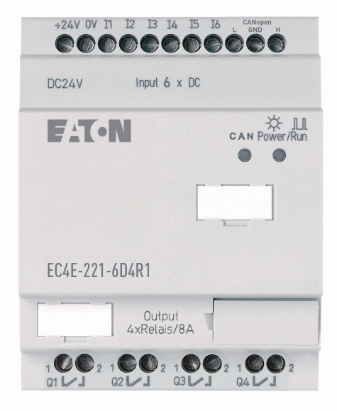
I/O expansion, integrated, 24 V DC, 6DI, 4DO(R)
I/O expansion via CANopen. Can be used for XC100/200, EC4P, XV-…
| Product range | Remote I/O systems Compact PLCs |
| Subrange | I/O expansions digital/analog |
| Basic function | Expansions |
| Description | usable via CANopen® |
| Function | CANopen® expansion EC4E |
| Inputs expansion (number) | |
| Real time clock | Digital: 6 |
| Supply voltage | |
| For use with | ✔ |
| For use with | 24 V DC |
| Dimensions (W x H x D) | XC100 XC200 EC4P |
| Weight | XC100/200, EC4P, MFD4 (via CANopen®) |
| Mounting | |
| Solid | 71.5 x 90 x 58 (4 PE) mm |
| Flexible with ferrule | 0.2 kg |
| Standard screwdriver | Top-hat rail IEC/EN 60715, 35 mm or screw fixing using fixing brackets ZB4-101-GF1 (accessories) |
| Max. tightening torque | |
| Operating ambient temperature | 0.2/4 (AWG 22 - 12) mm2 |
| Condensation | 0.2/2.5 (AWG 22 - 12) mm2 |
| Storage [ϑ] | 0.8 x 3.5 mm |
| Mounting position | 0.6 Nm |
| Overvoltage category/pollution degree | |
| Electrostatic discharge (ESD) >applied standard |
-25 to 55, cold as per IEC 60068-2-1, heat as per IEC 60068-2-2 °C |
| Electrostatic discharge (ESD) >Air discharge |
Take appropriate measures to prevent condensation |
| Electromagnetic fields (RFI) to IEC EN 61000-4-3 | -40 - +70 °C |
| Burst | |
| power pulses (Surge) | Vertical or horizontal |
| Immunity to line-conducted interference to (IEC/EN 61000-4-6) | |
| Clearance in air and creepage distances | II/2 |
| Insulation resistance | IEC EN 61000-4-2, Level 3 |
| Rated operational voltage [Ue] | 8 kV |
| Permissible range [Ue] | 10 V/m |
| Residual ripple | according to IEC/EN 61000-4-4 kV |
| Input current | 2 kV (supply cables, symmetrical, EASY...AC) 0.5 kV (supply cables, symmetrical, easy-DC) according to IEC/EN 61000-4-5 |
| Voltage dips | 10 V |
| Heat dissipation [P] | |
| CANopen® >Data transfer rate |
EN 50178, UL 508, CSA C22.2, No. 142 |
| CANopen® >Bus termination (first and last station) |
EN 50178 |
| CANopen® >Connection types |
|
| Mode slave >Stations |
24 DC (-15/+20%) V |
| Mode slave >PDO type |
20.4 - 28.8 V DC |
| Mode slave >Control contact rated current |
≦ 5 % |
| Number | 150 mA at Ue at no load |
| Potential isolation | ≤ 20 (IEC/EN 61131-2) ms |
| Rated operational voltage [Ue] | Normally 3.5 W |
| Input voltage | |
| Input current on 1 signal >Input current at signal 1 |
500 kBit/s, 25 m250 kBit/s, 40m125 kBit/s, 125 m50 kBit/s, 300 m20 kBit/s, 700 m10 kBit/s, 1000 m |
| Deceleration time | Via integrated Dip switch |
| Cable length | 2 x terminals (see terminal capacity) |
| Outputs in groups of | max. 62 Number |
| Parallel switching of outputs for increased output | Asynchronous, cyclic, acyclic |
| Protection of an output relay | to DS301V4 |
| Potential isolation | |
| Lifespan, mechanical [Operations] | 6 |
| Contacts >Conventional thermal current (10 A UL) |
from the outputs: yes |
| Contacts >Recommended for load: 12 V AC/DC |
24 V DC |
| Contacts >Short-circuit-proof cos ϕ = 1, characteristic B16 at 600 A |
< 5 (R1 - R6) at signal "0" > 15 (R1 - R6) at signal "1" V DC |
| Contacts >Short-circuit-proof cos ϕ = 0.5 to 0.7, characteristic B16 at 900 A |
3.3 (R1 to R6 (R12)) mA |
| Contacts >Rated impulse withstand voltage Uimp of contact coil |
20 (from “0” to “1”, debounce ON) Normally 0.25 (R1 - R12) (from “0” to “1”, debounce OFF) 20 (from „1“ to „0“) ms |
| Contacts >Rated operational voltage [Ue] |
100 (unshielded) m |
| Rated insulation voltage [Ui] | |
| Safe isolation according to EN 50178 | 1 |
| Breaking capacity >AC-15, 250 V AC, 3 A (600 Ops./h) [Operations] |
Not permissible |
| Breaking capacity >DC-13, L/R ≦ 150 ms, 24 V DC, 1 A (500 S/h) [Operations] |
Miniature circuit-breaker B16 or fuse 8 A (slow) |
| Filament bulb load >1000 W at 230/240 V AC [Operations] |
from power supply: yes From the inputs: yes to PC interface, memory card, network NET, easyLink Safe isolation according to EN 50178: 300 V AC Basic isolation: 600 V AC |
| Filament bulb load >500 W at 115/120 V AC [Operations] |
10 x 106 |
| Fluorescent lamp load >Fluorescent lamp load 10 x 58 W at 230/240 V AC >With upstream electrical device [Operations] |
6 A |
| Fluorescent lamp load >Fluorescent lamp load 10 x 58 W at 230/240 V AC >Uncompensated [Operations] |
> 500 mA |
| Fluorescent lamp load >Fluorescent lamp load 1 x 58 W at 230/240 V AC, conventional, compensated [Operations] |
16 A |
| Switching frequency >Mechanical operations |
16 A |
| Switching frequency >Switching frequency |
6 kV |
| Switching frequency >Resistive load/lamp load |
250 V AC |
| Switching frequency >Inductive load |
250 V AC |
| UL/CSA >Uninterrupted current at 240 V AC |
300 between coil and contact 300 between two contacts V AC |
| UL/CSA >Uninterrupted current at 24 V DC |
300000 |
| UL/CSA >AC >Control Circuit Rating Codes (utilization category) |
200000 |
| UL/CSA >AC >Max. rated operational voltage |
25000 |
| UL/CSA >AC >max. thermal continuous current cos ϕ = 1 at B 300 |
25000 |
| UL/CSA >AC >max. make/break cos ϕ ≠ capacity 1 at B 300 |
25000 |
| UL/CSA >DC >Control Circuit Rating Codes (utilization category) |
25000 |
| UL/CSA >DC >Max. rated operational voltage |
25000 |
| UL/CSA >DC >Max. thermal uninterrupted current at R 300 |
10 x 106 |
| UL/CSA >DC >Max. make/break capacity at R 300 |
10 Hz |
| Bus termination (first and last station) | 2 Hz |
| Rated operational current for specified heat dissipation [In] | 0.5 Hz |
| Heat dissipation per pole, current-dependent [Pvid] | 10 A |
| Equipment heat dissipation, current-dependent [Pvid] | 8 A |
| Static heat dissipation, non-current-dependent [Pvs] | B 300 Light Pilot Duty |
| Heat dissipation capacity [Pdiss] | 300 V AC |
| Operating ambient temperature min. | 5 A |
| Operating ambient temperature max. | 3600/360 VA |
| 10.2 Strength of materials and parts >10.2.2 Corrosion resistance |
R 300 Light Pilot Duty |
| 10.2 Strength of materials and parts >10.2.3.1 Verification of thermal stability of enclosures |
300 V DC |
| 10.2 Strength of materials and parts >10.2.3.2 Verification of resistance of insulating materials to normal heat |
1 A |
| 10.2 Strength of materials and parts >10.2.3.3 Verification of resistance of insulating materials to abnormal heat and fire due to internal electric effects |
28/28 VA |
| 10.2 Strength of materials and parts >10.2.4 Resistance to ultra-violet (UV) radiation |
|
| 10.2 Strength of materials and parts >10.2.5 Lifting |
Via integrated Dip switch |
| 10.2 Strength of materials and parts >10.2.6 Mechanical impact |
|
| 10.2 Strength of materials and parts >10.2.7 Inscriptions |
0 A |
| 10.3 Degree of protection of ASSEMBLIES | 0 W |
| 10.4 Clearances and creepage distances | 0 W |
| 10.5 Protection against electric shock | 3.4 W |
| 10.6 Incorporation of switching devices and components | 0 W |
| 10.7 Internal electrical circuits and connections | -25 °C |
| 10.8 Connections for external conductors | +55 °C |
| 10.9 Insulation properties >10.9.2 Power-frequency electric strength |
|
| 10.9 Insulation properties >10.9.3 Impulse withstand voltage |
Meets the product standard´s requirements. |
| 10.9 Insulation properties >10.9.4 Testing of enclosures made of insulating material |
Meets the product standard´s requirements. |
| 10.10 Temperature rise | Meets the product standard´s requirements. |
| 10.11 Short-circuit rating | Meets the product standard´s requirements. |
| 10.12 Electromagnetic compatibility | Meets the product standard´s requirements. |
| 10.13 Mechanical function | Does not apply, since the entire switchgear needs to be evaluated. |
| Supply voltage AC 50 Hz | Does not apply, since the entire switchgear needs to be evaluated. |
| Supply voltage AC 60 Hz | Meets the product standard´s requirements. |
| Supply voltage DC | Meets the product standard´s requirements. |
| Voltage type of supply voltage | Meets the product standard´s requirements. |
| Number of digital inputs | Does not apply, since the entire switchgear needs to be evaluated. |
| Number of digital outputs | Does not apply, since the entire switchgear needs to be evaluated. |
| Digital inputs configurable | Is the panel builder´s responsibility. |
| Digital outputs configurable | Is the panel builder´s responsibility. |
| Input current at signal 1 | Is the panel builder´s responsibility. |
| Permitted voltage at input | Is the panel builder´s responsibility. |
| Type of voltage (input voltage) | Is the panel builder´s responsibility. |
| Type of digital output | The panel builder is responsible for the temperature rise calculation. Eaton will provide heat dissipation data for the devices. |
| Output current | Is the panel builder´s responsibility. |
| Permitted voltage at output | Is the panel builder´s responsibility. |
| Type of output voltage | The device meets the requirements, provided the information in the instruction leaflet (IL) is observed. |
| Short-circuit protection, outputs available | |
| Redundancy | |
| Type of electric connection | 0 - 0 V |
| Time delay at signal exchange | 0 - 0 V |
| Suitable for safety functions | 20.4 - 28.8 V |
| Category according to EN 954-1 | DC |
| SIL according to IEC 61508 | 6 |
| Performance level acc. EN ISO 13849-1 | 4 |
| Appendant operation agent (Ex ia) | No |
| Appendant operation agent (Ex ib) | No |
| Explosion safety category for gas | 3.3 mA |
| Explosion safety category for dust | 0 - 0 V |
| Width | DC |
| Height | Relay |
| Depth | 8 A |
| North America Certification | 0 - 0 V |
| Specially designed for North America | AC/DC |
| Current Limiting Circuit-Breaker | No |
| Degree of Protection | No |
Tüm hakları saklıdır. Mnelko Endüstriyel San. ve Tic.Ltd.Şti. 2024