SKU: Eaton-107646
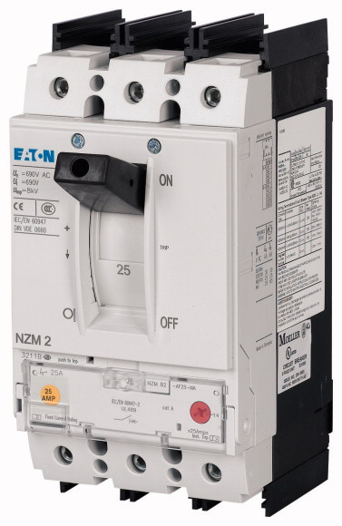
Circuit-breaker, 3p, 150A, box terminals
Series NZM..-AF..NA circuit-breakers cover all application cases with just four compact sizes and are suitable for use in the worldwide market. Modular function groups always make mounting flexible. With thermomagnetic releases for systems and cable protection. Fixed overload releases. Notes: Switches conform to UL/CSA as well as IEC regulations. The rating plate contains IEC switching performance values.
| Product range | Circuit-breaker | ||||||||||||
| Protective function | System and cable protection | ||||||||||||
| Standard/Approval | UL/CSA, IEC | ||||||||||||
| Release system | Thermomagnetic release | ||||||||||||
| Installation type | Fixed | ||||||||||||
| Description | Switches conform to UL/CSA as well as the IEC regulations. IEC switching performance values are contained on the rating plate. Fixed overload releases Ir |
||||||||||||
| Frame size | NZM2 | ||||||||||||
| Number of poles | 3 pole | ||||||||||||
| Standard equipment | Box terminal | ||||||||||||
| SCCR 480Y/277 V 60 Hz [Icu] | 35 kA | ||||||||||||
| SCCR 480 V 60 Hz [Icu] | 35 kA | ||||||||||||
| SCCR 600Y/347 V 60 Hz [Icu] | 25 kA | ||||||||||||
| Rated current = rated uninterrupted current [In = Iu] | 150 A | ||||||||||||
| Overload trip 150 - 150 A
Short-circuit releases >Non-delayed |
150 - 150 A | ||||||||||||
| Standards | 6 - 10 | ||||||||||||
| Protection against direct contact | IEC/EN 60947 | ||||||||||||
| Climatic proofing | Finger and back of hand proof to VDE 0106 Part 100 | ||||||||||||
| Ambient temperature >Ambient temperature, storage |
Damp heat, constant, to IEC 60068-2-78 Damp heat, cyclic, to IEC 60068-2-30 |
||||||||||||
| Ambient temperature >Operation |
- 40 - + 70 °C | ||||||||||||
| Mechanical shock resistance (10 ms half-sinusoidal shock) according to IEC 60068-2-27 | -25 - +70 °C | ||||||||||||
| Safe isolation to EN 61140 >Between auxiliary contacts and main contacts |
20 (half-sinusoidal shock 20 ms) g | ||||||||||||
| Safe isolation to EN 61140 >between the auxiliary contacts |
500 V AC | ||||||||||||
| Weight | 300 V AC | ||||||||||||
| Mounting position >Mounting position |
2.345 kg | ||||||||||||
| Direction of incoming supply |
|
||||||||||||
| Degree of protection >Device |
as required | ||||||||||||
| Degree of protection >Enclosures |
In the operating controls area: IP20 (basic degree of protection) | ||||||||||||
| Degree of protection >Terminations |
With insulating surround: IP40 With door coupling rotary handle: IP66 |
||||||||||||
| Other technical data (sheet catalogue) | Tunnel terminal: IP10 Phase isolator and strip terminal: IP00 |
||||||||||||
| Rated surge voltage invariability [Uimp
] >Main contacts |
Weight Temperature dependency, Derating Effective power loss |
||||||||||||
| Rated surge voltage invariability [Uimp
] >Auxiliary contacts |
8000 V | ||||||||||||
| Rated operational voltage [Ue] | 6000 V | ||||||||||||
| Overvoltage category/pollution degree | 690 V AC | ||||||||||||
| Rated insulation voltage [Ui ] | III/3 | ||||||||||||
| Use in unearthed supply systems | 1000 V | ||||||||||||
| Rated short-circuit making capacity [Icm
] >240 V [Icm ] |
≦ 690 V | ||||||||||||
| Rated short-circuit making capacity [Icm
] >400/415 V [Icm ] |
187 kA | ||||||||||||
| Rated short-circuit making capacity [Icm
] >440 V 50/60 Hz [Icm ] |
105 kA | ||||||||||||
| Rated short-circuit making capacity [Icm
] >525 V 50/60 Hz [Icm ] |
74 kA | ||||||||||||
| Rated short-circuit making capacity [Icm
] >690 V 50/60 H [Ic] |
53 kA | ||||||||||||
| Rated short-circuit breaking capacity Icn [Icn
] >Icu to IEC/EN 60947 test cycle O-t-CO [Icu] >240 V 50/60 Hz [Icu ] |
40 kA | ||||||||||||
| Rated short-circuit breaking capacity Icn [Icn
] >Icu to IEC/EN 60947 test cycle O-t-CO [Icu] >400/415 V 50/60 Hz [Icu ] |
85 kA | ||||||||||||
| Rated short-circuit breaking capacity Icn [Icn
] >Icu to IEC/EN 60947 test cycle O-t-CO [Icu] >440 V 50/60 Hz [Icu ] |
50 kA | ||||||||||||
| Rated short-circuit breaking capacity Icn [Icn
] >Icu to IEC/EN 60947 test cycle O-t-CO [Icu] >525 V 50/60 Hz [Icu ] |
35 kA | ||||||||||||
| Rated short-circuit breaking capacity Icn [Icn
] >Icu to IEC/EN 60947 test cycle O-t-CO [Icu] >690 V 50/60 Hz [Icu ] |
25 kA | ||||||||||||
| Rated short-circuit breaking capacity Icn [Icn
] >Ics to IEC/EN 60947 test cycle O-t-CO-t-CO [Ics] >240 V 50/60 Hz [Ics ] |
20 kA | ||||||||||||
| Rated short-circuit breaking capacity Icn [Icn
] >Ics to IEC/EN 60947 test cycle O-t-CO-t-CO [Ics] >400/415 V 50/60 Hz [Ics ] |
85 kA | ||||||||||||
| Rated short-circuit breaking capacity Icn [Icn
] >Ics to IEC/EN 60947 test cycle O-t-CO-t-CO [Ics] >440 V 50/60 Hz [Ics ] |
50 kA | ||||||||||||
| Rated short-circuit breaking capacity Icn [Icn
] >Ics to IEC/EN 60947 test cycle O-t-CO-t-CO [Ics] >525 V 50/60 Hz [Ics ] |
35 kA | ||||||||||||
| Rated short-circuit breaking capacity Icn [Icn
] >Ics to IEC/EN 60947 test cycle O-t-CO-t-CO [Ics] >690 V 50/60 Hz [Ics] |
25 kA | ||||||||||||
| Rated short-circuit breaking capacity Icn [Icn
] >Maximum low-voltage h.b.c. fuse |
5 kA | ||||||||||||
| Rated short-circuit breaking capacity Icn [Icn ] | 355 A gG/gL | ||||||||||||
| Technical data that diverge from products for the IEC market Switching capacity of NA switches (UL489, CSA 22.2 No. 5.1) Short-circuit current rating SCCR >SCCR 240 V 60 Hz [Icu] |
Maximum back-up fuse, if the expected short-circuit currents at the installation location exceed the switching capacity of the circuit-breaker. | ||||||||||||
| Technical data that diverge from products for the IEC market Switching capacity of NA switches (UL489, CSA 22.2 No. 5.1) Short-circuit current rating SCCR >SCCR 480Y/277 V 60 Hz [Icu] |
85 kA | ||||||||||||
| Technical data that diverge from products for the IEC market Switching capacity of NA switches (UL489, CSA 22.2 No. 5.1) Short-circuit current rating SCCR >SCCR 480 V 60 Hz [Icu] |
35 kA | ||||||||||||
| Technical data that diverge from products for the IEC market Switching capacity of NA switches (UL489, CSA 22.2 No. 5.1) Short-circuit current rating SCCR >SCCR 600Y/347 V 60 Hz [Icu] |
35 kA | ||||||||||||
| Rated short-time withstand current >t = 0.3 s [Icw ] |
25 kA | ||||||||||||
| Rated short-time withstand current >t = 1 s [Icw ] |
1.9 kA | ||||||||||||
| Utilization category to IEC/EN 60947-2 | 1.9 kA | ||||||||||||
| Lifespan, mechanical(of which max. 50 % trip by shunt/undervoltage release) [Operations] | A | ||||||||||||
| Lifespan, electrical >AC-1 >400 V 50/60 Hz [Operations] |
20000 | ||||||||||||
| Lifespan, electrical >AC-1 >690 V 50/60 Hz [Operations] |
10000 | ||||||||||||
| Lifespan, electrical >AC--3 >400 V 50/60 Hz [Operations] |
7500 | ||||||||||||
| Lifespan, electrical >AC--3 >415 V 50/60 Hz [Operations] |
6500 | ||||||||||||
| Lifespan, electrical >AC--3 >690 V 50/60 Hz [Operations] |
6500 | ||||||||||||
| Lifespan, electrical >Max. operating frequency |
5000 | ||||||||||||
| Total break time at short-circuit | 120 Ops/h | ||||||||||||
| Standard equipment | < 10 ms | ||||||||||||
| Round copper conductor >Box terminal >Solid |
Box terminal | ||||||||||||
| Round copper conductor >Box terminal >Stranded |
1 x (12 … 6) mm2 | ||||||||||||
| Round copper conductor >Tunnel terminal >Solid |
1 x (4 … 350) mm2 | ||||||||||||
| Round copper conductor >Tunnel terminal >Stranded >Stranded |
1 x 16 mm2 | ||||||||||||
| Round copper conductor >Bolt terminal and rear-side connection >Direct on the switch >Solid |
1 x (4 … 350) mm2 | ||||||||||||
| Round copper conductor >Bolt terminal and rear-side connection >Direct on the switch >Stranded |
1 x (11 … 6) mm2 | ||||||||||||
| Al conductors, Cu cable >Tunnel terminal >Solid |
1 x (4 … 3/0) mm2 | ||||||||||||
| Al conductors, Cu cable >Bolt terminal and rear-side connection >Flat copper strip, with holes [min.] |
1 x 16 mm2 | ||||||||||||
| Al conductors, Cu cable >Bolt terminal and rear-side connection >Flat copper strip, with holes [max.] |
2 x 16 x 0.8 mm | ||||||||||||
| Cu strip (number of segments x width x segment thickness) >Box terminal [min.] |
10 x 16 x 0.8 mm | ||||||||||||
| Cu strip (number of segments x width x segment thickness) >Box terminal [max.] |
2 x 9 x 0.8 mm | ||||||||||||
| Cu strip (number of segments x width x segment thickness) >Bolt terminal and rear-side connection >Flat copper strip, with holes [min.] |
10 x 16 x 0.8 mm | ||||||||||||
| Cu strip (number of segments x width x segment thickness) >Bolt terminal and rear-side connection >Flat copper strip, with holes [max.] |
2 x 16 x 0.8 mm | ||||||||||||
| Copper busbar (width x thickness) [mm] >Bolt terminal and rear-side connection >Screw connection |
10 x 16 x 0.8 mm | ||||||||||||
| Copper busbar (width x thickness) [mm] >Bolt terminal and rear-side connection >Direct on the switch [min.] |
M8 | ||||||||||||
| Copper busbar (width x thickness) [mm] >Bolt terminal and rear-side connection >Direct on the switch [max.] |
16 x 5 mm | ||||||||||||
| Control cables | 20 x 5 mm | ||||||||||||
| Rated operational current for specified heat dissipation [In] | 1 x (18 … 14) 2 x (18 … 16) mm2 |
||||||||||||
| Equipment heat dissipation, current-dependent [Pvid] | 150 A | ||||||||||||
| Operating ambient temperature min. | 33.75 W | ||||||||||||
| Operating ambient temperature max. | -25 °C | ||||||||||||
| 10.2 Strength of materials and parts >10.2.2 Corrosion resistance |
+70 °C | ||||||||||||
| 10.2 Strength of materials and parts >10.2.3.1 Verification of thermal stability of enclosures |
Meets the product standard´s requirements. | ||||||||||||
| 10.2 Strength of materials and parts >10.2.3.2 Verification of resistance of insulating materials to normal heat |
Meets the product standard´s requirements. | ||||||||||||
| 10.2 Strength of materials and parts >10.2.3.3 Verification of resistance of insulating materials to abnormal heat and fire due to internal electric effects |
Meets the product standard´s requirements. | ||||||||||||
| 10.2 Strength of materials and parts >10.2.4 Resistance to ultra-violet (UV) radiation |
Meets the product standard´s requirements. | ||||||||||||
| 10.2 Strength of materials and parts >10.2.5 Lifting |
Meets the product standard´s requirements. | ||||||||||||
| 10.2 Strength of materials and parts >10.2.6 Mechanical impact |
Does not apply, since the entire switchgear needs to be evaluated. | ||||||||||||
| 10.2 Strength of materials and parts >10.2.7 Inscriptions |
Does not apply, since the entire switchgear needs to be evaluated. | ||||||||||||
| 10.3 Degree of protection of ASSEMBLIES | Meets the product standard´s requirements. | ||||||||||||
| 10.4 Clearances and creepage distances | Does not apply, since the entire switchgear needs to be evaluated. | ||||||||||||
| 10.5 Protection against electric shock | Meets the product standard´s requirements. | ||||||||||||
| 10.6 Incorporation of switching devices and components | Does not apply, since the entire switchgear needs to be evaluated. | ||||||||||||
| 10.7 Internal electrical circuits and connections | Does not apply, since the entire switchgear needs to be evaluated. | ||||||||||||
| 10.8 Connections for external conductors | Is the panel builder´s responsibility. | ||||||||||||
| 10.9 Insulation properties >10.9.2 Power-frequency electric strength |
Is the panel builder´s responsibility. | ||||||||||||
| 10.9 Insulation properties >10.9.3 Impulse withstand voltage |
Is the panel builder´s responsibility. | ||||||||||||
| 10.9 Insulation properties >10.9.4 Testing of enclosures made of insulating material |
Is the panel builder´s responsibility. | ||||||||||||
| 10.10 Temperature rise | Is the panel builder´s responsibility. | ||||||||||||
| 10.11 Short-circuit rating | The panel builder is responsible for the temperature rise calculation. Eaton will provide heat dissipation data for the devices. | ||||||||||||
| 10.12 Electromagnetic compatibility | Is the panel builder´s responsibility. The specifications for the switchgear must be observed. | ||||||||||||
| 10.13 Mechanical function | Is the panel builder´s responsibility. The specifications for the switchgear must be observed. | ||||||||||||
| Rated permanent current Iu | The device meets the requirements, provided the information in the instruction leaflet (IL) is observed. | ||||||||||||
| Rated voltage | 150 A | ||||||||||||
| Rated short-circuit breaking capacity lcu at 400 V, 50 Hz | 690 - 690 V | ||||||||||||
| Overload release current setting | 50 kA | ||||||||||||
| Adjustment range short-term delayed short-circuit release | 150 - 150 A | ||||||||||||
| Adjustment range undelayed short-circuit release | 0 - 0 A | ||||||||||||
| Integrated earth fault protection | 6 - 10 A | ||||||||||||
| Type of electrical connection of main circuit | No | ||||||||||||
| Device construction | Frame clamp | ||||||||||||
| Suitable for DIN rail (top hat rail) mounting | Built-in device fixed built-in technique | ||||||||||||
| DIN rail (top hat rail) mounting optional | No | ||||||||||||
| Number of auxiliary contacts as normally closed contact | Yes | ||||||||||||
| Number of auxiliary contacts as normally open contact | 0 | ||||||||||||
| Number of auxiliary contacts as change-over contact | 0 | ||||||||||||
| With switched-off indicator | 0 | ||||||||||||
| With under voltage release | No | ||||||||||||
| Number of poles | No | ||||||||||||
| Position of connection for main current circuit | 3 | ||||||||||||
| Type of control element | Front side | ||||||||||||
| Complete device with protection unit | Rocker lever | ||||||||||||
| Motor drive integrated | Yes | ||||||||||||
| Motor drive optional | No | ||||||||||||
| Degree of protection (IP) | Yes | ||||||||||||
| Product Standards | IP20 | ||||||||||||
| UL File No. | UL 489; CSA-C22.2 No. 5-09; IEC 60947-2; CE marking | ||||||||||||
| UL Category Control No. | E31593 | ||||||||||||
| CSA File No. | DIVQ | ||||||||||||
| CSA Class No. | 022086 | ||||||||||||
| North America Certification | 1432-01 | ||||||||||||
| Specially designed for North America | UL listed, CSA certified | ||||||||||||
| Suitable for | Yes | ||||||||||||
| Current Limiting Circuit-Breaker | Feeder circuits, branch circuits | ||||||||||||
| Max. Voltage Rating | Yes | ||||||||||||
| Degree of Protection | 600Y/347 V, 480 V | ||||||||||||
| Characteristic curve | IEC: IP20; UL/CSA Type: - | ||||||||||||
| Characteristic curve | |||||||||||||
| Characteristic curve | |||||||||||||
Tüm hakları saklıdır. Mnelko Endüstriyel San. ve Tic.Ltd.Şti. 2024