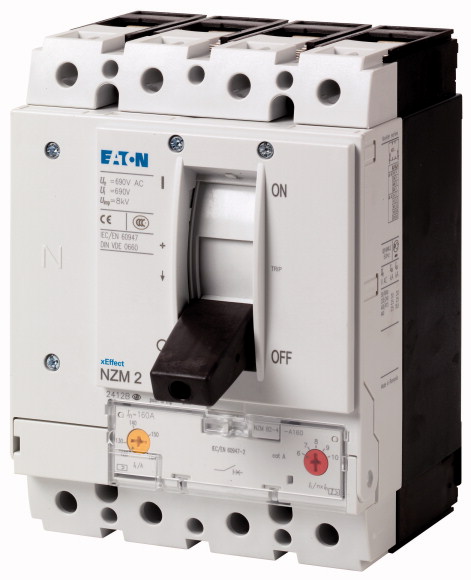
SKU: Eaton-107583
Circuit-breaker, 4p, 300A, 200A in 4th pole
Circuit-breaker NZM2, 4 pole, Switching capacity 400/415 V 50 Hz( Icu ): 25 kA, Rated current = rated uninterrupted current Rated current = rated uninterrupted current( In = Iu ): 300 A, Installation type: Fixed, Screw connection, Standard/Approval: IEC, Protective function: System and cable protection
| Product range | Circuit-breaker | ||||||||||||
| Protective function | System and cable protection | ||||||||||||
| Standard/Approval | IEC | ||||||||||||
| Installation type | Fixed | ||||||||||||
| Release system | Thermomagnetic release | ||||||||||||
| Construction size | NZM2 | ||||||||||||
| Description | Set value in neutral conductor is synchronous with set value Ir of main pole. | ||||||||||||
| Number of poles | 4 pole | ||||||||||||
| Standard equipment | Screw connection | ||||||||||||
| 400/415 V 50 Hz [Icu ] | 25 kA | ||||||||||||
| Rated current = rated uninterrupted current [In = Iu] | 300 A | ||||||||||||
| Neutral conductor [% of phase conductor] | 60 CSA | ||||||||||||
| Reduced neutral conductor protection | 200 A | ||||||||||||
| Neutral conductor protection | Reduced neutral conductor protection | ||||||||||||
| Overload trip 240 - 300 A
Overload trip >Main pole |
240 - 300 A | ||||||||||||
| Short-circuit releases >Non-delayed |
160 - 200 A | ||||||||||||
| Short-circuit releases |
5 - 8.3 | ||||||||||||
| Standards | 2000 - 2500 A | ||||||||||||
| Protection against direct contact | IEC/EN 60947 | ||||||||||||
| Climatic proofing | Finger and back of hand proof to VDE 0106 Part 100 | ||||||||||||
| Ambient temperature >Ambient temperature, storage |
Damp heat, constant, to IEC 60068-2-78 Damp heat, cyclic, to IEC 60068-2-30 |
||||||||||||
| Ambient temperature >Operation |
- 40 - + 70 °C | ||||||||||||
| Mechanical shock resistance (10 ms half-sinusoidal shock) according to IEC 60068-2-27 | -25 - +70 °C | ||||||||||||
| Safe isolation to EN 61140 >Between auxiliary contacts and main contacts |
20 (half-sinusoidal shock 20 ms) g | ||||||||||||
| Safe isolation to EN 61140 >between the auxiliary contacts |
500 V AC | ||||||||||||
| Weight | 300 V AC | ||||||||||||
| Mounting position | 3.5 kg | ||||||||||||
| Direction of incoming supply |
|
||||||||||||
| Degree of protection >Device |
as required | ||||||||||||
| Degree of protection >Enclosures |
In the operating controls area: IP20 (basic degree of protection) | ||||||||||||
| Degree of protection >Terminations |
With insulating surround: IP40 With door coupling rotary handle: IP66 |
||||||||||||
| Other technical data (sheet catalogue) | Tunnel terminal: IP10 Phase isolator and strip terminal: IP00 |
||||||||||||
| Rated current = rated uninterrupted current [In = Iu] | Temperature dependency, Derating | ||||||||||||
| Rated surge voltage invariability [Uimp
] >Main contacts |
300 A | ||||||||||||
| Rated surge voltage invariability [Uimp
] >Auxiliary contacts |
8000 V | ||||||||||||
| Rated operational voltage [Ue] | 6000 V | ||||||||||||
| Overvoltage category/pollution degree | 440 V AC | ||||||||||||
| Rated insulation voltage [Ui ] | III/3 | ||||||||||||
| Use in unearthed supply systems | 690 V | ||||||||||||
| Rated short-circuit making capacity [Icm
] >240 V [Icm ] |
≦ 440 V | ||||||||||||
| Rated short-circuit making capacity [Icm
] >400/415 V [Icm ] |
63 kA | ||||||||||||
| Rated short-circuit making capacity [Icm
] >440 V 50/60 Hz [Icm ] |
53 kA | ||||||||||||
| Rated short-circuit breaking capacity Icn [Icn
] >Icu to IEC/EN 60947 test cycle O-t-CO [Icu] >240 V 50/60 Hz [Icu ] |
53 kA | ||||||||||||
| Rated short-circuit breaking capacity Icn [Icn
] >Icu to IEC/EN 60947 test cycle O-t-CO [Icu] >400/415 V 50/60 Hz [Icu ] |
30 kA | ||||||||||||
| Rated short-circuit breaking capacity Icn [Icn
] >Icu to IEC/EN 60947 test cycle O-t-CO [Icu] >440 V 50/60 Hz [Icu ] |
25 kA | ||||||||||||
| Rated short-circuit breaking capacity Icn [Icn
] >Ics to IEC/EN 60947 test cycle O-t-CO-t-CO [Ics] >240 V 50/60 Hz [Ics ] |
25 kA | ||||||||||||
| Rated short-circuit breaking capacity Icn [Icn
] >Ics to IEC/EN 60947 test cycle O-t-CO-t-CO [Ics] >400/415 V 50/60 Hz [Ics ] |
30 kA | ||||||||||||
| Rated short-circuit breaking capacity Icn [Icn
] >Ics to IEC/EN 60947 test cycle O-t-CO-t-CO [Ics] >440 V 50/60 Hz [Ics ] |
25 kA | ||||||||||||
| Rated short-circuit breaking capacity Icn [Icn ] | 18.5 kA | ||||||||||||
| Utilization category to IEC/EN 60947-2 | Maximum back-up fuse, if the expected short-circuit currents at the installation location exceed the switching capacity of the circuit-breaker. | ||||||||||||
| Lifespan, mechanical(of which max. 50 % trip by shunt/undervoltage release) [Operations] | A | ||||||||||||
| Lifespan, electrical >AC-1 >400 V 50/60 Hz [Operations] |
20000 | ||||||||||||
| Lifespan, electrical >AC-1 >415 V 50/60 Hz [Operations] |
10000 | ||||||||||||
| Lifespan, electrical >Max. operating frequency |
7500 | ||||||||||||
| Total break time at short-circuit | 120 Ops/h | ||||||||||||
| Standard equipment | < 10 ms | ||||||||||||
| Optional accessories | Screw connection | ||||||||||||
| Round copper conductor >Box terminal >Solid |
Box terminal Tunnel terminal connection on rear |
||||||||||||
| Round copper conductor >Box terminal >Stranded |
1 x (10 - 16) 2 x (6 - 16) mm2 |
||||||||||||
| Round copper conductor >Tunnel terminal >Solid |
1 x (25 - 185) 2 x (25 - 70) mm2 |
||||||||||||
| Round copper conductor >Tunnel terminal >Stranded >1-hole |
1 x 16 mm2 | ||||||||||||
| Round copper conductor >Bolt terminal and rear-side connection >Direct on the switch >Solid |
1 x (25 - 185) mm2 | ||||||||||||
| Round copper conductor >Bolt terminal and rear-side connection >Direct on the switch >Stranded |
1 x (10 - 16) 2 x (6 - 16) mm2 |
||||||||||||
| Al circular conductor >Tunnel terminal >Solid |
1 x (25 - 185) 2 x (25 - 70) mm2 |
||||||||||||
| Al circular conductor >Tunnel terminal >Stranded >Stranded |
1 x 16 mm2 | ||||||||||||
| Al circular conductor >Bolt terminal and rear-side connection >Direct on the switch >Solid |
1 x (25 - 185) mm2 | ||||||||||||
| Al circular conductor >Bolt terminal and rear-side connection >Direct on the switch >Stranded |
1 x (10 - 16) 2 x (10 - 16) mm2 |
||||||||||||
| Cu strip (number of segments x width x segment thickness) >Box terminal [min.] |
1 x (25 - 50) 2 x (25 - 50) mm2 |
||||||||||||
| Cu strip (number of segments x width x segment thickness) >Box terminal [max.] |
2 x 9 x 0.8 mm | ||||||||||||
| Cu strip (number of segments x width x segment thickness) >Bolt terminal and rear-side connection >Flat copper strip, with holes [min.] |
10 x 16 x 0.8 (2x) 8 x 15.5 x 0,8 mm |
||||||||||||
| Cu strip (number of segments x width x segment thickness) >Bolt terminal and rear-side connection >Flat copper strip, with holes [max.] |
2 x 16 x 0.8 mm | ||||||||||||
| Copper busbar (width x thickness) [mm] >Bolt terminal and rear-side connection >Screw connection |
10 x 24 x 0.8 mm | ||||||||||||
| Copper busbar (width x thickness) [mm] >Bolt terminal and rear-side connection >Direct on the switch [min.] |
M8 | ||||||||||||
| Copper busbar (width x thickness) [mm] >Bolt terminal and rear-side connection >Direct on the switch [max.] |
16 x 5 mm | ||||||||||||
| Control cables | 24 x 8 mm | ||||||||||||
| Rated operational current for specified heat dissipation [In] | 1 x (0.75 - 2.5) 2 x (0.75 - 1.5) mm2 |
||||||||||||
| Equipment heat dissipation, current-dependent [Pvid] | 300 A | ||||||||||||
| Operating ambient temperature min. | 83.7 W | ||||||||||||
| Operating ambient temperature max. | -25 °C | ||||||||||||
| 10.2 Strength of materials and parts >10.2.2 Corrosion resistance |
+70 °C | ||||||||||||
| 10.2 Strength of materials and parts >10.2.3.1 Verification of thermal stability of enclosures |
Meets the product standard´s requirements. | ||||||||||||
| 10.2 Strength of materials and parts >10.2.3.2 Verification of resistance of insulating materials to normal heat |
Meets the product standard´s requirements. | ||||||||||||
| 10.2 Strength of materials and parts >10.2.3.3 Verification of resistance of insulating materials to abnormal heat and fire due to internal electric effects |
Meets the product standard´s requirements. | ||||||||||||
| 10.2 Strength of materials and parts >10.2.4 Resistance to ultra-violet (UV) radiation |
Meets the product standard´s requirements. | ||||||||||||
| 10.2 Strength of materials and parts >10.2.5 Lifting |
Meets the product standard´s requirements. | ||||||||||||
| 10.2 Strength of materials and parts >10.2.6 Mechanical impact |
Does not apply, since the entire switchgear needs to be evaluated. | ||||||||||||
| 10.2 Strength of materials and parts >10.2.7 Inscriptions |
Does not apply, since the entire switchgear needs to be evaluated. | ||||||||||||
| 10.3 Degree of protection of ASSEMBLIES | Meets the product standard´s requirements. | ||||||||||||
| 10.4 Clearances and creepage distances | Does not apply, since the entire switchgear needs to be evaluated. | ||||||||||||
| 10.5 Protection against electric shock | Meets the product standard´s requirements. | ||||||||||||
| 10.6 Incorporation of switching devices and components | Does not apply, since the entire switchgear needs to be evaluated. | ||||||||||||
| 10.7 Internal electrical circuits and connections | Does not apply, since the entire switchgear needs to be evaluated. | ||||||||||||
| 10.8 Connections for external conductors | Is the panel builder´s responsibility. | ||||||||||||
| 10.9 Insulation properties >10.9.2 Power-frequency electric strength |
Is the panel builder´s responsibility. | ||||||||||||
| 10.9 Insulation properties >10.9.3 Impulse withstand voltage |
Is the panel builder´s responsibility. | ||||||||||||
| 10.9 Insulation properties >10.9.4 Testing of enclosures made of insulating material |
Is the panel builder´s responsibility. | ||||||||||||
| 10.10 Temperature rise | Is the panel builder´s responsibility. | ||||||||||||
| 10.11 Short-circuit rating | The panel builder is responsible for the temperature rise calculation. Eaton will provide heat dissipation data for the devices. | ||||||||||||
| 10.12 Electromagnetic compatibility | Is the panel builder´s responsibility. The specifications for the switchgear must be observed. | ||||||||||||
| 10.13 Mechanical function | Is the panel builder´s responsibility. The specifications for the switchgear must be observed. | ||||||||||||
| Rated permanent current Iu | The device meets the requirements, provided the information in the instruction leaflet (IL) is observed. | ||||||||||||
| Rated voltage | 300 A | ||||||||||||
| Rated short-circuit breaking capacity lcu at 400 V, 50 Hz | 440 - 440 V | ||||||||||||
| Overload release current setting | 25 kA | ||||||||||||
| Adjustment range short-term delayed short-circuit release | 240 - 300 A | ||||||||||||
| Adjustment range undelayed short-circuit release | 0 - 0 A | ||||||||||||
| Integrated earth fault protection | 5 - 8.3 A | ||||||||||||
| Type of electrical connection of main circuit | No | ||||||||||||
| Device construction | Screw connection | ||||||||||||
| Suitable for DIN rail (top hat rail) mounting | Built-in device fixed built-in technique | ||||||||||||
| DIN rail (top hat rail) mounting optional | No | ||||||||||||
| Number of auxiliary contacts as normally closed contact | Yes | ||||||||||||
| Number of auxiliary contacts as normally open contact | 0 | ||||||||||||
| Number of auxiliary contacts as change-over contact | 0 | ||||||||||||
| With switched-off indicator | 0 | ||||||||||||
| With under voltage release | No | ||||||||||||
| Number of poles | No | ||||||||||||
| Position of connection for main current circuit | 4 | ||||||||||||
| Type of control element | Front side | ||||||||||||
| Complete device with protection unit | Rocker lever | ||||||||||||
| Motor drive integrated | Yes | ||||||||||||
| Motor drive optional | No | ||||||||||||
| Degree of protection (IP) | Yes | ||||||||||||
| Characteristic curve | IP20 | ||||||||||||
| Characteristic curve | |||||||||||||
| Characteristic curve | |||||||||||||
Tüm hakları saklıdır. Mnelko Endüstriyel San. ve Tic.Ltd.Şti. 2024