SKU: Eaton-106858
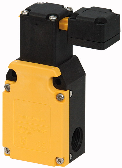
Safety position switch, LS(4)…ZB, Safety position switches, Complete unit, 1 N/O, 1 NC, wide, Insulated material, Screw terminal, -25 - +70 °C
Safety position switch, Basic function: Position switches, Safety position switches, Part group reference: LS(4)…ZB, Product range: Safety position switches, Degree of Protection: IP65, Features: Complete unit, Ambient temperature: -25 - +70 °C, Description: With the actuator inserted, the N/O contact is open and the NC contact is closed., Contacts N/O = Normally open: 1 N/O, Contacts N/C = Normally closed: 1 NC, Notes: = safety function, by positive opening to IEC/EN 60947-5-1, Housing: Insulated material, Connection type: Screw terminal, Standards: IEC/EN 60947
| Basic function | Position switches Safety position switches |
| Part group reference | LS(4)…ZB |
| Product range | Safety position switches |
| Degree of Protection | IP65 |
| Features | Complete unit |
| Ambient temperature | -25 - +70 °C |
| Design | wide |
| Description | With the actuator inserted, the N/O contact is open and the NC contact is closed. |
| Approval | |
| N/O = Normally open | 1 N/O |
| N/C = Normally closed | 1 NC  |
| Notes | = safety function, by positive opening to IEC/EN 60947-5-1 |
| Contact sequence | |
| Contact travel■ = Contact closed□ = Contact open | |
| Housing | Insulated material |
| Connection type | Screw terminal |
| Notes | Do not, under any circumstance, use the switch as a mechanical stop or transportation restraint or brace! Connect operating elements permanently with the protective device, e.g., with non-reusable screws or rivets. Operating head can be rotated 90°. |
| Standards | IEC/EN 60947 |
| Climatic proofing | Damp heat, constant, to IEC 60068-2-78; damp heat, cyclical, to IEC 60068-2-30 |
| Ambient temperature | -25 - +70 °C |
| Mounting position | As required |
| Degree of Protection | IP65 |
| Terminal capacities >Solid |
1 x (0.75 - 2.5) 2 x (0.75 - 1.5) mm2 |
| Terminal capacities >Flexible with ferrule |
1 x (0.5 - 1.5) 2 x (0.5 - 1.5) mm2 |
| Terminal screw | PH1 |
| Tightening torque for terminal screw | 0.9 Nm |
| Repetition accuracy | 0.02 mm |
| Rated impulse withstand voltage [Uimp] | 6000 V AC |
| Rated insulation voltage [Ui ] | 500 V |
| Overvoltage category/pollution degree | III/3 |
| Rated operational current [Ie
] >AC-15 >24 V [Ie ] |
6 A |
| Rated operational current [Ie
] >AC-15 >220 V 230 V 240 V [Ie] |
6 A |
| Rated operational current [Ie
] >AC-15 >380 V 400 V 415 V [Ie] |
4 A |
| Rated operational current [Ie
] >DC-13 >24 V [Ie ] |
3 A |
| Rated operational current [Ie
] >DC-13 >110 V [Ie ] |
0.8 A |
| Rated operational current [Ie
] >DC-13 >220 V [Ie ] |
0.3 A |
| Supply frequency | max. 400 Hz |
| Short-circuit rating to IEC/EN 60947-5-1 >max. fuse |
10 A gG/gL |
| Rated conditional short-circuit current | 1 kA |
| Lifespan, mechanical [Operations] | 1.5 x 10⁶ |
| Mechanical shock resistance (half-sinusoidal shock, 20 ms) >Standard-action contact |
5 g |
| Operating frequency [Operations/h] | ≦ 1800 |
| Mechanical >Actuating force at beginning/end of stroke |
15/20 (plug-in/pull-out) N |
| Rated operational current for specified heat dissipation [In] | 6 A |
| Heat dissipation per pole, current-dependent [Pvid] | 0.1 W |
| Equipment heat dissipation, current-dependent [Pvid] | 0 W |
| Static heat dissipation, non-current-dependent [Pvs] | 0 W |
| Heat dissipation capacity [Pdiss] | 0 W |
| Operating ambient temperature min. | -25 °C |
| Operating ambient temperature max. | +70 °C |
| 10.2 Strength of materials and parts >10.2.2 Corrosion resistance |
Meets the product standard´s requirements. |
| 10.2 Strength of materials and parts >10.2.3.1 Verification of thermal stability of enclosures |
Meets the product standard´s requirements. |
| 10.2 Strength of materials and parts >10.2.3.2 Verification of resistance of insulating materials to normal heat |
Meets the product standard´s requirements. |
| 10.2 Strength of materials and parts >10.2.3.3 Verification of resistance of insulating materials to abnormal heat and fire due to internal electric effects |
Meets the product standard´s requirements. |
| 10.2 Strength of materials and parts >10.2.4 Resistance to ultra-violet (UV) radiation |
Meets the product standard´s requirements. |
| 10.2 Strength of materials and parts >10.2.5 Lifting |
Does not apply, since the entire switchgear needs to be evaluated. |
| 10.2 Strength of materials and parts >10.2.6 Mechanical impact |
Does not apply, since the entire switchgear needs to be evaluated. |
| 10.2 Strength of materials and parts >10.2.7 Inscriptions |
Meets the product standard´s requirements. |
| 10.3 Degree of protection of ASSEMBLIES | Does not apply, since the entire switchgear needs to be evaluated. |
| 10.4 Clearances and creepage distances | Meets the product standard´s requirements. |
| 10.5 Protection against electric shock | Does not apply, since the entire switchgear needs to be evaluated. |
| 10.6 Incorporation of switching devices and components | Does not apply, since the entire switchgear needs to be evaluated. |
| 10.7 Internal electrical circuits and connections | Is the panel builder´s responsibility. |
| 10.8 Connections for external conductors | Is the panel builder´s responsibility. |
| 10.9 Insulation properties >10.9.2 Power-frequency electric strength |
Is the panel builder´s responsibility. |
| 10.9 Insulation properties >10.9.3 Impulse withstand voltage |
Is the panel builder´s responsibility. |
| 10.9 Insulation properties >10.9.4 Testing of enclosures made of insulating material |
Is the panel builder´s responsibility. |
| 10.10 Temperature rise | The panel builder is responsible for the temperature rise calculation. Eaton will provide heat dissipation data for the devices. |
| 10.11 Short-circuit rating | Is the panel builder´s responsibility. The specifications for the switchgear must be observed. |
| 10.12 Electromagnetic compatibility | Is the panel builder´s responsibility. The specifications for the switchgear must be observed. |
| 10.13 Mechanical function | The device meets the requirements, provided the information in the instruction leaflet (IL) is observed. |
| Width sensor | 40 mm |
| Diameter sensor | 0 mm |
| Height of sensor | 125 mm |
| Length of sensor | 40 mm |
| Rated operation current Ie at AC-15, 24 V | 10 A |
| Rated operation current Ie at AC-15, 125 V | 6 A |
| Rated operation current Ie at AC-15, 230 V | 6 A |
| Rated operation current Ie at DC-13, 24 V | 3 A |
| Rated operation current Ie at DC-13, 125 V | 0.8 A |
| Rated operation current Ie at DC-13, 230 V | 0.3 A |
| Switching function | Slow-action switch |
| Switching function latching | No |
| Output electronic | No |
| Forced opening | Yes |
| Number of safety auxiliary contacts | 0 |
| Number of contacts as normally closed contact | 0 |
| Number of contacts as normally open contact | 0 |
| Number of contacts as change-over contact | 0 |
| Type of interface | None |
| Type of interface for safety communication | None |
| Construction type housing | Cuboid |
| Material housing | Plastic |
| Coating housing | Other |
| Type of control element | Other |
| Alignment of the control element | Other |
| Type of electric connection | Cable entry metrical |
| With status indication | No |
| Suitable for safety functions | Yes |
| Explosion safety category for gas | None |
| Explosion safety category for dust | None |
| Ambient temperature during operating | 25 - 70 °C |
| Degree of protection (IP) | IP65 |
| Degree of protection (NEMA) | 13 |
| Product Standards | IEC/EN 60947-5; UL 508; CSA-C22.2 No. 14; CE marking |
| UL File No. | E29184 |
| UL Category Control No. | NKCR |
| CSA File No. | 12528 |
| CSA Class No. | 3211-03 |
| North America Certification | UL listed, CSA certified |
| Degree of Protection | IEC: IP65, UL/CSA Type 3R, 4X (indoor use only), 12, 13 |
Tüm hakları saklıdır. Mnelko Endüstriyel San. ve Tic.Ltd.Şti. 2024