SKU: Eaton-101455
Busbar adapter, 45 mm, 16 A, DIN rail: 2
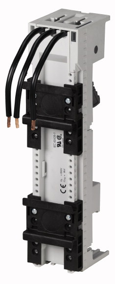
45mm busbar adapter for 60mm busbar system, two mounting rails, three prefabricated cables (AWG14/2.5 square millimeter) for connection of switching device with spring-loaded terminals in the feeder circuit, can be used for motor-protective circuit-breaker PKZM0-…-C or motor-starter combination with PKZM0-…-C and contactor DILM(C)7 to DILM(C)15, rated operational current: 16A, rated operational current according to UL508: 12A
| Accessories | Busbar adapters |
| For use with | Approved to UL 508 For fitting to flat Cu-busbars with 60 mm between busbar centres, suitable for 5 mm and 10 mm busbar thickness Rated operational current 16 A For starter with springloaded terminals |
| Rated operational voltage [Ue] | Busbar adapters PKZ0 |
| Rated operational current [Ie] | 690 V |
| Terminal capacity | 16 A |
| Adapter width | AWG 14 (2.5 mm²) |
| Adapter length | 45 mm |
| DIN rail | 200 mm |
| Adapter width | 2 Quantity |
| For use with | 45 mm |
| Notes | PKZM0-C + DILMC7 PKZM0-C + DILMC9 PKZM0-C + DILMC12 |
| Rated operational current for specified heat dissipation [In] | According to UL 508: Ie = 12 A |
| Heat dissipation per pole, current-dependent [Pvid] | 16 A |
| Equipment heat dissipation, current-dependent [Pvid] | 0 W |
| Static heat dissipation, non-current-dependent [Pvs] | 0.8 W |
| Heat dissipation capacity [Pdiss] | 0 W |
| Operating ambient temperature min. | 0 W |
| Operating ambient temperature max. | -25 °C |
| 10.2 Strength of materials and parts >10.2.2 Corrosion resistance |
+55 °C |
| 10.2 Strength of materials and parts >10.2.3.1 Verification of thermal stability of enclosures |
Meets the product standard´s requirements. |
| 10.2 Strength of materials and parts >10.2.3.2 Verification of resistance of insulating materials to normal heat |
Meets the product standard´s requirements. |
| 10.2 Strength of materials and parts >10.2.3.3 Verification of resistance of insulating materials to abnormal heat and fire due to internal electric effects |
Meets the product standard´s requirements. |
| 10.2 Strength of materials and parts >10.2.4 Resistance to ultra-violet (UV) radiation |
Meets the product standard´s requirements. |
| 10.2 Strength of materials and parts >10.2.5 Lifting |
Meets the product standard´s requirements. |
| 10.2 Strength of materials and parts >10.2.6 Mechanical impact |
Does not apply, since the entire switchgear needs to be evaluated. |
| 10.2 Strength of materials and parts >10.2.7 Inscriptions |
Does not apply, since the entire switchgear needs to be evaluated. |
| 10.3 Degree of protection of ASSEMBLIES | Meets the product standard´s requirements. |
| 10.4 Clearances and creepage distances | Does not apply, since the entire switchgear needs to be evaluated. |
| 10.5 Protection against electric shock | Meets the product standard´s requirements. |
| 10.6 Incorporation of switching devices and components | Does not apply, since the entire switchgear needs to be evaluated. |
| 10.7 Internal electrical circuits and connections | Does not apply, since the entire switchgear needs to be evaluated. |
| 10.8 Connections for external conductors | Is the panel builder´s responsibility. |
| 10.9 Insulation properties >10.9.2 Power-frequency electric strength |
Is the panel builder´s responsibility. |
| 10.9 Insulation properties >10.9.3 Impulse withstand voltage |
Is the panel builder´s responsibility. |
| 10.9 Insulation properties >10.9.4 Testing of enclosures made of insulating material |
Is the panel builder´s responsibility. |
| 10.10 Temperature rise | Is the panel builder´s responsibility. |
| 10.11 Short-circuit rating | The panel builder is responsible for the temperature rise calculation. Eaton will provide heat dissipation data for the devices. |
| 10.12 Electromagnetic compatibility | Is the panel builder´s responsibility. The specifications for the switchgear must be observed. |
| 10.13 Mechanical function | Is the panel builder´s responsibility. The specifications for the switchgear must be observed. |
| Mounting rail armament | The device meets the requirements, provided the information in the instruction leaflet (IL) is observed. |
| Type of electric connection | 2 mounting rails |
| Rated current In | Round conductor |
| Min. busbar thickness | 16 A |
| Max. busbar thickness | 5 mm |
| Width of the adapter | 10 mm |
| Rail width | 45 mm |
| Busbar distance | 35 mm |
| Product Standards | 60 mm |
| UL File No. | UL 508A; CSA-C22.2 No. 14; IEC60439-1; CE marking |
| UL Category Control No. | E300273 |
| North America Certification | NMTR; NMTR7 |
| Specially designed for North America | UL listed, certified by UL for use in Canada |
| Max. Voltage Rating | No |
Tüm hakları saklıdır. Mnelko Endüstriyel San. ve Tic.Ltd.Şti. 2024