SKU: Eaton-72898
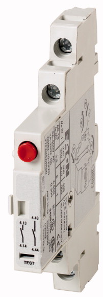
Trip indicator, 2 x 1 N/O, Screw terminals
Trip indicator switch 2 N/O, with screw terminal, for circuit-breaker PKZ(M)0 size
| Product range | Accessories |
| Accessories | Trip-indicating auxiliary contacts |
| N/O = Normally open | Differential status indication a) General trip indication (overload) b) Short-circuit release Short-circuits indicated locally by means of a red indicator that can be manually reset |
| Contact diagram | |
| Contact sequence | 2 x 1 N/O |
| Connection technique | |
| For use with | |
| For use with | |
| Can be combined with auxiliary contact | Screw terminals |
| Notes | Trip indicator PKZ0(4), PKE |
| Rated impulse withstand voltage [Uimp] | PKZM0 PKZM4 PKZM0-T PKM0 PKZM01 PKE |
| Overvoltage category/pollution degree | NHI11-PKZ0 NHI12-PKZ0 NHI21-PKZ0 NHI-E-... |
| Rated operational voltage [Ue] [Ue ] | Can be fitted to the right of: Motor protective circuit-breaker |
| Safe isolation to EN 61140 >Between auxiliary contacts and main contacts |
|
| Rated operational current [Ie
] >AC-15 >220 - 240 V [Ie] |
6000 V AC |
| Rated operational current [Ie
] >AC-15 >380 - 415 V [Ie] |
III/3 |
| Rated operational current [Ie
] >AC-15 >440 V 500 V [Ie] |
250 V DC |
| Rated operational current [Ie
] >DC-13 L/R - 100 ms >24 V [Ie ] |
690 V AC |
| Rated operational current [Ie
] >DC-13 L/R - 100 ms >60 V [Ie ] |
3.5 A |
| Rated operational current [Ie
] >DC-13 L/R - 100 ms >110 V [Ie ] |
2 A |
| Rated operational current [Ie
] >DC-13 L/R - 100 ms >220 V [Ie ] |
1 A |
| Lifespan >Lifespan, mechanical [Operations] |
2 A |
| Lifespan >Lifespan, electrical [Operations] |
1 A |
| Control circuit reliability [Failure rate] | 0.5 A |
| Short-circuit rating without welding >Fuseless |
0.25 A |
| Short-circuit rating without welding >Fuse |
> 0.01 x 10⁶ |
| Solid or flexible conductor, with ferrule | 0.05 x 10⁶ |
| Solid or stranded | <10-8, < one failure at 100 million operations (at Ue = 24 V DC, Umin = 17 V, Imin = 5.4 mA) λ |
| Pilot Duty >AC operated |
FAZ-B4/1-HI Type |
| Pilot Duty >DC operated |
10 A gG/gL |
| General Use >AC |
|
| General Use >AC |
0,75 - 2,5 mm2 |
| General Use >DC |
18 - 14 AWG |
| General Use >DC |
|
| Rated operational current for specified heat dissipation [In] | A600 |
| Heat dissipation per pole, current-dependent [Pvid] | Q300 |
| Equipment heat dissipation, current-dependent [Pvid] | 600 V |
| Static heat dissipation, non-current-dependent [Pvs] | 5 A |
| Heat dissipation capacity [Pdiss] | 250 V |
| Operating ambient temperature min. | 1 A |
| Operating ambient temperature max. | |
| 10.2 Strength of materials and parts >10.2.2 Corrosion resistance |
3.5 A |
| 10.2 Strength of materials and parts >10.2.3.1 Verification of thermal stability of enclosures |
0.1 W |
| 10.2 Strength of materials and parts >10.2.3.2 Verification of resistance of insulating materials to normal heat |
0 W |
| 10.2 Strength of materials and parts >10.2.3.3 Verification of resistance of insulating materials to abnormal heat and fire due to internal electric effects |
0 W |
| 10.2 Strength of materials and parts >10.2.4 Resistance to ultra-violet (UV) radiation |
0 W |
| 10.2 Strength of materials and parts >10.2.5 Lifting |
-25 °C |
| 10.2 Strength of materials and parts >10.2.6 Mechanical impact |
+55 °C |
| 10.2 Strength of materials and parts >10.2.7 Inscriptions |
|
| 10.3 Degree of protection of ASSEMBLIES | Meets the product standard´s requirements. |
| 10.4 Clearances and creepage distances | Meets the product standard´s requirements. |
| 10.5 Protection against electric shock | Meets the product standard´s requirements. |
| 10.6 Incorporation of switching devices and components | Meets the product standard´s requirements. |
| 10.7 Internal electrical circuits and connections | Meets the product standard´s requirements. |
| 10.8 Connections for external conductors | Does not apply, since the entire switchgear needs to be evaluated. |
| 10.9 Insulation properties >10.9.2 Power-frequency electric strength |
Does not apply, since the entire switchgear needs to be evaluated. |
| 10.9 Insulation properties >10.9.3 Impulse withstand voltage |
Meets the product standard´s requirements. |
| 10.9 Insulation properties >10.9.4 Testing of enclosures made of insulating material |
Does not apply, since the entire switchgear needs to be evaluated. |
| 10.10 Temperature rise | Meets the product standard´s requirements. |
| 10.11 Short-circuit rating | Does not apply, since the entire switchgear needs to be evaluated. |
| 10.12 Electromagnetic compatibility | Does not apply, since the entire switchgear needs to be evaluated. |
| 10.13 Mechanical function | Is the panel builder´s responsibility. |
| Number of contacts as change-over contact | Is the panel builder´s responsibility. |
| Number of contacts as normally open contact | Is the panel builder´s responsibility. |
| Number of contacts as normally closed contact | Is the panel builder´s responsibility. |
| Number of fault-signal switches | Is the panel builder´s responsibility. |
| Rated operation current Ie at AC-15, 230 V | The panel builder is responsible for the temperature rise calculation. Eaton will provide heat dissipation data for the devices. |
| Type of electric connection | Is the panel builder´s responsibility. The specifications for the switchgear must be observed. |
| Model | Is the panel builder´s responsibility. The specifications for the switchgear must be observed. |
| Mounting method | The device meets the requirements, provided the information in the instruction leaflet (IL) is observed. |
| Lamp holder | |
| Product Standards | |
| UL File No. | 0 |
| UL Category Control No. | 2 |
| CSA File No. | 0 |
| CSA Class No. | 1 |
| North America Certification | 3.5 A |
| Specially designed for North America | Screw connection |
| Accessories | Top mounting |
Tüm hakları saklıdır. Mnelko Endüstriyel San. ve Tic.Ltd.Şti. 2024