SKU: Eaton-63959
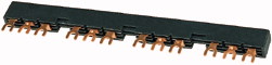
Three-phase busbar link, Circuit-breaker: 4, 234 mm, For PKZM0-... or PKE12, PKE32 without side mounted auxiliary contacts or voltage releases
Three-phase busbar link 3 poles for feeder unit of 4 PKZM0-... with auxiliary contact or trip indicator built onto the right side or a voltage release built onto the left side, length 108mm protective against direct contact., Ue = 690 V, Iu = 63 A
| Product range | Accessories |
| Accessories | Three-phase busbar link |
| For use with | Protected against accidental contact, short-circuit proof, Ue = 690 V, Iu = 63 A Can be extended by rotating by installation For PKZM0-... or PKE attached on the right with an auxiliary contact and a trip indicating signal or attached on the left with a voltage release |
| Circuit-breaker | Three-phase commoning link PKZ0, PKE12, PKE32 |
| Length | 4 Number |
| Unit width | 234 mm |
| Notes | 45 + 18 mm |
| Rated impulse withstand voltage [Uimp] | For parallel power feed to several motor-protective circuit-breakers on terminals 1, 3, 5 |
| Overvoltage category/pollution degree | |
| Rated operational voltage [Ue] | 6000 V AC |
| Rated uninterrupted current [Iu] | III/3 |
| Rated operational current for specified heat dissipation [In] | 690 V AC |
| Heat dissipation per pole, current-dependent [Pvid] | 63 A |
| Equipment heat dissipation, current-dependent [Pvid] | |
| Static heat dissipation, non-current-dependent [Pvs] | 63 A |
| Heat dissipation capacity [Pdiss] | 2.5 W |
| Operating ambient temperature min. | 7.5 W |
| Operating ambient temperature max. | 0 W |
| 10.2 Strength of materials and parts >10.2.2 Corrosion resistance |
0 W |
| 10.2 Strength of materials and parts >10.2.3.1 Verification of thermal stability of enclosures |
-25 °C |
| 10.2 Strength of materials and parts >10.2.3.2 Verification of resistance of insulating materials to normal heat |
+55 °C |
| 10.2 Strength of materials and parts >10.2.3.3 Verification of resistance of insulating materials to abnormal heat and fire due to internal electric effects |
|
| 10.2 Strength of materials and parts >10.2.4 Resistance to ultra-violet (UV) radiation |
Meets the product standard´s requirements. |
| 10.2 Strength of materials and parts >10.2.5 Lifting |
Meets the product standard´s requirements. |
| 10.2 Strength of materials and parts >10.2.6 Mechanical impact |
Meets the product standard´s requirements. |
| 10.2 Strength of materials and parts >10.2.7 Inscriptions |
Meets the product standard´s requirements. |
| 10.3 Degree of protection of ASSEMBLIES | Meets the product standard´s requirements. |
| 10.4 Clearances and creepage distances | Does not apply, since the entire switchgear needs to be evaluated. |
| 10.5 Protection against electric shock | Does not apply, since the entire switchgear needs to be evaluated. |
| 10.6 Incorporation of switching devices and components | Meets the product standard´s requirements. |
| 10.7 Internal electrical circuits and connections | Does not apply, since the entire switchgear needs to be evaluated. |
| 10.8 Connections for external conductors | Meets the product standard´s requirements. |
| 10.9 Insulation properties >10.9.2 Power-frequency electric strength |
Does not apply, since the entire switchgear needs to be evaluated. |
| 10.9 Insulation properties >10.9.3 Impulse withstand voltage |
Does not apply, since the entire switchgear needs to be evaluated. |
| 10.9 Insulation properties >10.9.4 Testing of enclosures made of insulating material |
Is the panel builder´s responsibility. |
| 10.10 Temperature rise | Is the panel builder´s responsibility. |
| 10.11 Short-circuit rating | Is the panel builder´s responsibility. |
| 10.12 Electromagnetic compatibility | Is the panel builder´s responsibility. |
| 10.13 Mechanical function | Is the panel builder´s responsibility. |
| Number of phases | The panel builder is responsible for the temperature rise calculation. Eaton will provide heat dissipation data for the devices. |
| Number of poles | Is the panel builder´s responsibility. The specifications for the switchgear must be observed. |
| Suitable for number of devices | Is the panel builder´s responsibility. The specifications for the switchgear must be observed. |
| Pitch dimensions | The device meets the requirements, provided the information in the instruction leaflet (IL) is observed. |
| Cross section | |
| Length | |
| Number of modular spacings | 3 |
| Rated permanent current Iu | 3 |
| Type of electric connection | 4 |
| Insulated | 63 mm |
| Rated surge voltage | 0 mm² |
| Conditioned rated short-circuit current Iq | 234 mm |
| Max. rated operation voltage Ue | 0 |
| Rated short-time withstand current lcw | 63 A |
| Suitable for devices with N-busbar | Fork |
| Suitable for devices with auxiliary switch | Yes |
| Product Standards | 6 kV |
| UL File No. | 0 kA |
| UL Category Control No. | 690 V |
| CSA File No. | 0 kA |
| CSA Class No. | No |
| North America Certification | No |
| Specially designed for North America | UL 508; CSA-C22.2 No. 14; IEC60947-4-1; CE marking |
Tüm hakları saklıdır. Mnelko Endüstriyel San. ve Tic.Ltd.Şti. 2024