SKU: Eaton-000699
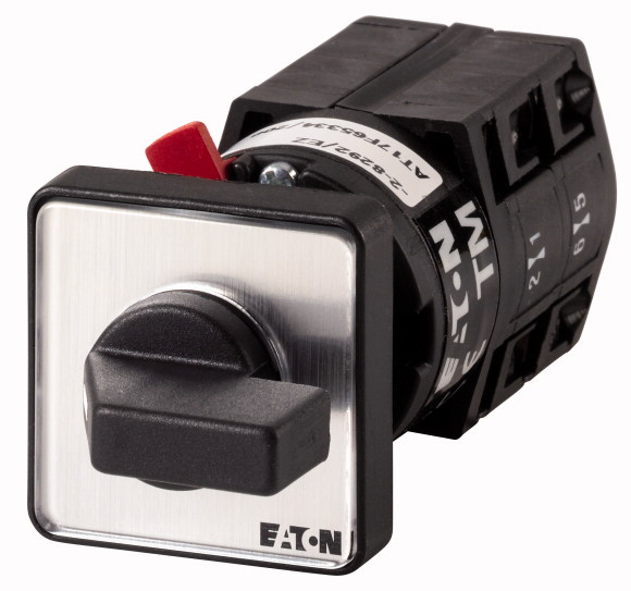
Coding switches, TM, 10 A, centre mounting, 2 contact unit(s), Contacts: 4, 30 °, maintained, With 0 (Off) position, 0-9, Design number 8550
Coding switch, Product range: Control switches, Standards: IEC/EN 60947, VDE 0660, CSA, UL, Control switch as per IEC/EN 60947-5-1, Auxiliary switch as per IEC/EN 60947-5-1, Part group reference: TM, with black thumb grip and front plate, Contacts: 4, Degree of Protection: Front IP65, Design: centre mounting, switching function: BCD Code 0-9, Switching angle: 30 °, Switching performance: maintained, With 0 (Off) position, 2 contact unit(s), Rated uninterrupted current: Iu= 10 A, front plate: 0-9
| Product range | Control switches |
| Part group reference | TM |
| Basic function | Coding switches |
| Contacts | with black thumb grip and front plate |
| Degree of Protection | 4 |
| Design | Front IP65 |
| Contact sequence | centre mounting |
| switching function | |
| Switching angle | |
| Switching performance | BCD Code 0-9 |
| Design number | 30 ° |
| Front plate no. | maintained With 0 (Off) position |
| front plate | 8550 |
| 400 V [P] | |
| Rated uninterrupted current [Iu] | 0-9 |
| Note on rated uninterrupted current !u | 3 kW |
| Number of contact units | 10 A |
| Standards | Rated uninterrupted current Iu is specified for max. cross-section. |
| Climatic proofing | 2 contact unit(s) |
| Ambient temperature >Open |
IEC/EN 60947, VDE 0660, CSA, UL Control switch as per IEC/EN 60947-5-1 Auxiliary switch as per IEC/EN 60947-5-1 |
| Overvoltage category/pollution degree | Damp heat, constant, to IEC 60068-2-78 Damp heat, cyclic, to IEC 60068-2-30 |
| Rated impulse withstand voltage [Uimp] | -25 - +50 °C |
| Mounting position | III/3 |
| Electrical characteristics >Rated operational voltage [Ue] |
4000 V AC |
| Electrical characteristics >Rated uninterrupted current [Iu] |
As required |
| Electrical characteristics >Note on rated uninterrupted current !u |
500 V AC |
| Short-circuit rating >Fuse |
10 A |
| Safe isolation to EN 61140 >Current heat loss per contact at Ie |
Rated uninterrupted current Iu is specified for max. cross-section. |
| Safe isolation to EN 61140 >Current heat loss per auxiliary circuit at Ie (AC-15/230 V) |
10 A gG/gL |
| Lifespan, mechanical [Operations] | 0.15 W |
| Maximum operating frequency [Operations/h] | 0.15 CO |
| AC >AC-23A >Motor rating AC-23A, 50 - 60 Hz [P] >400 V 415 V [P] |
> 1 x 10⁶ |
| Control circuit reliability at 24 V DC, 10 mA [Fault probability] | 1200 |
| Solid or stranded | 3 kW |
| Flexible with ferrules to DIN 46228 | < 10 -5, < 1 fault in 100000 operations HF |
| Flexible | 1 x 1,5 2 x 1,5 mm2 |
| Terminal screw | 1 x 1.0 2 x 1.0 mm2 |
| Tightening torque for terminal screw | 1 x 1.5 2 x 1.5 mm2 |
| Contacts >Rated operational voltage [Ue] |
M2.5 |
| Contacts >Rated uninterrupted current max. >Main conducting paths >General use |
0.4 Nm |
| Contacts >Rated uninterrupted current max. >Auxiliary contacts >General Use [IU] |
300 V AC |
| Contacts >Rated uninterrupted current max. >Auxiliary contacts >Pilot Duty |
10 A |
| Switching capacity >Maximum motor rating >Single-phase >120 V AC |
10 A |
| Switching capacity >Maximum motor rating >Single-phase >240 V AC |
A 300 |
| Switching capacity >Maximum motor rating >Single-phase >277 V AC |
0.33 HP |
| Switching capacity >Maximum motor rating >Three-phase >120 V AC |
0.75 HP |
| Switching capacity >Maximum motor rating >Three-phase >240 V AC |
0.75 HP |
| Terminal capacity >Solid or flexible conductor with ferrule |
0.75 HP |
| Terminal capacity >Terminal screw |
1 HP |
| Terminal capacity >Tightening torque |
14 AWG |
| Rated operational current for specified heat dissipation [In] | M2.5 |
| Heat dissipation per pole, current-dependent [Pvid] | 3.5 lb-in |
| Equipment heat dissipation, current-dependent [Pvid] | 10 A |
| Static heat dissipation, non-current-dependent [Pvs] | 0.15 W |
| Heat dissipation capacity [Pdiss] | 0 W |
| Operating ambient temperature min. | 0 W |
| Operating ambient temperature max. | 0 W |
| 10.2 Strength of materials and parts >10.2.2 Corrosion resistance |
-25 °C |
| 10.2 Strength of materials and parts >10.2.3.1 Verification of thermal stability of enclosures |
+50 °C |
| 10.2 Strength of materials and parts >10.2.3.2 Verification of resistance of insulating materials to normal heat |
Meets the product standard´s requirements. |
| 10.2 Strength of materials and parts >10.2.3.3 Verification of resistance of insulating materials to abnormal heat and fire due to internal electric effects |
Meets the product standard´s requirements. |
| 10.2 Strength of materials and parts >10.2.4 Resistance to ultra-violet (UV) radiation |
Meets the product standard´s requirements. |
| 10.2 Strength of materials and parts >10.2.5 Lifting |
Meets the product standard´s requirements. |
| 10.2 Strength of materials and parts >10.2.6 Mechanical impact |
UV resistance only in connection with protective shield. |
| 10.2 Strength of materials and parts >10.2.7 Inscriptions |
Does not apply, since the entire switchgear needs to be evaluated. |
| 10.3 Degree of protection of ASSEMBLIES | Does not apply, since the entire switchgear needs to be evaluated. |
| 10.4 Clearances and creepage distances | Meets the product standard´s requirements. |
| 10.5 Protection against electric shock | Does not apply, since the entire switchgear needs to be evaluated. |
| 10.6 Incorporation of switching devices and components | Meets the product standard´s requirements. |
| 10.7 Internal electrical circuits and connections | Does not apply, since the entire switchgear needs to be evaluated. |
| 10.8 Connections for external conductors | Does not apply, since the entire switchgear needs to be evaluated. |
| 10.9 Insulation properties >10.9.2 Power-frequency electric strength |
Is the panel builder´s responsibility. |
| 10.9 Insulation properties >10.9.3 Impulse withstand voltage |
Is the panel builder´s responsibility. |
| 10.9 Insulation properties >10.9.4 Testing of enclosures made of insulating material |
Is the panel builder´s responsibility. |
| 10.10 Temperature rise | Is the panel builder´s responsibility. |
| 10.11 Short-circuit rating | Is the panel builder´s responsibility. |
| 10.12 Electromagnetic compatibility | The panel builder is responsible for the temperature rise calculation. Eaton will provide heat dissipation data for the devices. |
| 10.13 Mechanical function | Is the panel builder´s responsibility. The specifications for the switchgear must be observed. |
| Type of switch | Is the panel builder´s responsibility. The specifications for the switchgear must be observed. |
| Number of poles | The device meets the requirements, provided the information in the instruction leaflet (IL) is observed. |
| Max. rated operation voltage Ue AC | Coding switch |
| Rated permanent current Iu | 1 |
| Number of switch positions | 500 V |
| With 0 (off) position | 10 A |
| With retraction in 0-position | 10 |
| Device construction | Yes |
| Width in number of modular spacings | No |
| Suitable for ground mounting | Built-in device |
| Suitable for front mounting 4-hole | 0 |
| Suitable for distribution board installation | No |
| Suitable for intermediate mounting | Yes |
| Complete device in housing | No |
| Type of control element | No |
| Front shield size | No |
| Degree of protection (IP), front side | Toggle |
| Degree of protection (NEMA), front side | 30x30 mm |
| Product Standards | IP65 |
| UL File No. | Other |
| UL Category Control No. | UL 508; CSA-C22.2 No. 14-05; CSA-C22.2 No. 94; IEC/EN 60947-3; CE marking |
| CSA File No. | E36332 |
| North America Certification | NLRV |
| Degree of Protection | UL report applies to both US and Canada |
Tüm hakları saklıdır. Mnelko Endüstriyel San. ve Tic.Ltd.Şti. 2024